Benutzer-Werkzeuge
Inhaltsverzeichnis
AxisControl-Compact
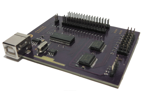
Die Baugruppe ist funktionskompatibel zum ITRA-AxisControl, alle Bauteile und Steckverbinder sind aber auf nur einer Leiterplatte gleicher Größe angeordnet.
Mit der Baugruppe können 8 Analog-Eingänge und 32 Schalter abgefragt und als Game-Controller im System eingebunden werden. An den Steckplätzen für die Analogeingänge liegen eine Referenzspannung und Masse an, so dass der Analogwert über einen Schieberegler oder ein Drehpotentiometer gebildet werden kann.
Installation
Es werden Windows-Systeme ab WindowsXP unterstützt. Gegenüber dem ITRA-AxisControl ist die Firmware jetzt im EEPROM abgelegt und der Controller meldet sich gleich als HID-Gerät im System an.
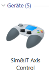
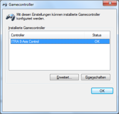
Nach erfolgreicher Installation wird der USB-Controller als Gamecontroller mit der Bezeichnung Sim&IT Axis Control vom Betriebssystem erkannt. Die Konfiguration und Kalibrierung erfolgt dann über:
Windows7: Start → Systemsteuerung → Geräte und Drucker → Auswahl des Controllers
Windows10: Start → Windows-System → Systemsteuerung → Hardware und Sound → Geräte und Drucker → Auswahl des Controllers
Die Zuordnung der Flugsimulatorsteuerachsen zu den Achsen des Sim&IT Axis Control und die der Tasten erfolgt im Flugsimulator unter Optionen → Steuerungen.
Schaltplan
Bestückung des AC-Compact

Belegung der Steckverbinder
J1 - USB-Anschluss
Die Baugruppe besitzt einen USB-Fullspeed-Controller.
J2 - Erweiterung
Steckverbinder J2 ist nicht bestückt, kann aber für Erweiterungen nachträglich nachbestückt werder. Die Belegung ist:
        1   2
5P      o   o 5P
3,3P    o   o 3,3P
I²C     o   o I²C
I²C     o   o I²C
GND     o   o GND
        9   10
Die 3,3V-Versorgung kann mit 100mA belastet werden. Die I²C-Anschlüsse sind nur zur internen Verwendung vorgesehen.
J3 und J4 (Taster)
An diese beiden Steckverbinder können mit einem zweiploigen Steckverbinder 32 Taster angeschlossen werden.
Diese Taster müssen in jedem Fall potentialfrei sein und dürfen nicht mit anderen Tastern eine elektrische Verbindung haben.
J7 - Schalter
Ein Schalter an J7 hat eine spezielle Bedeutung. Wenn der Schalter geschlossen wird, werden alle Ereignisse, die von den Tastern an J3 und J4 erzeugt werden, nicht verarbeitet. Dies kann u.U. bei der Achsenkalibrierung notwendig sein, wenn an den Analogachsen auch Taster z.B. zur Anschlagserkennung angebracht sind. In der Windows Gamecontroller Kalibrierung beenden Tastenereignisse die Kalibrierung oder schalten zur nächsten Achse.
J8 (Coolie Heat)
o  Cooliehat unten/vorn
o  Cooliehat rechts
o  Cooliehat oben/hinten
o  Cooliehat links
o  Masse
J11 bis J18 (Potentiometer)
Für die 8 Achsen des Controllers sind dreipolige Steckverbinder vorgesehen.
o  o  o
|  |  |
|  |  Referenzspannung +3,3V
|  Analogeingang
Analog-GND
Zwischen Referenzspannung und Analog-GND können z.B. 100kOhm-Potentiometer angeschlossen werden, der Abgriff des Potentiometers wird an den Analogeingang angeschlossen. An den Analogeingang kann auch eine Steuerspannung zwischen 0 und 3,3V in Bezug auf AGND angelegt werden.
Offene Signal-Eingänge sollten mit einem Kurzschluss-Stecker (Jumper) nach Analog-GND verbunden werden.
Die Referenzspannung darf nicht zur Versorgung weiterer Elektronik verwendet werden. Hierfür könnte J2 mit bis zu 100mA genutzt werden.
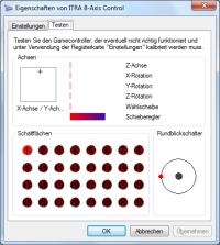
Es gilt folgende Windows-Achsenzuordnung beim Gamecontroller:
Axis-01  X-Achse
Axis-02  Y-Achse
Axis-03  Z-Achse
Axis-04  Schieberegler
Axis-05  X-Rotation
Axis-06  Y-Rotation
Axis-07  Z-Rotation
Axis-08  Wählscheibe
AxisControl-Compact (english)
The module is functionally compatible with the ITRA-AxisControl, but all components and connectors are arranged on just one printed circuit board of the same size.
With the module, 8 analog inputs and 32 switches can be queried and integrated as a game controller in the system. A reference voltage and ground are applied to the slots for the analog inputs, so that the analog value can be formed via a slider or a rotary potentiometer.
Installation
It supports Windows systems as of WindowsXP. Compared to the ITRA-AxisControl, the firmware is now stored in the EEPROM and the controller logs in immediately as an HID device in the system.
After successful installation, the USB controller will be recognized by the operating system as a game controller named Sim&IT Axis Control. The configuration and calibration will be done via:
Windows7: Start → Control Panel → Devices and Printers → Selection of the Controller
Windows10: Start → Windows System → Control Panel → Hardware and Sound → Devices and Printers → Selection of the Controller
The assignment of the flight simulator control axes to the axes of the Sim&IT Axis Control and the keys is done in the flight simulator under Options → Controls .
Circuit Diagram
Assembly of the AC-Compact
Assignment of the connectors
J1 - USB connector
The module has a USB full-speed controller.
J2 - Extension
Connector J2 is not equipped, but can be retrofitted later for expansions. The occupancy is:
        1   2
5P      o   o 5P
3.3P    o   o 3.3P
I²C     o   o I²C
I²C     o   o I²C
GND     o   o GND
        9   10
The 3.3V supply can be loaded with 100mA. The I²C connections are for internal use only.
J3 und J4 (Push button)
32 push buttons can be connected to these two connectors with a two-pole connector.
These buttons must always be potential-free and must not have any electrical connection with any other button.
J7 - Switch
A switch at J7 has a special meaning. When the switch is closed, any events generated by the buttons at J3 and J4 will not be processed. This may in some circumstances be necessary in the axis calibration, if on the analog axes also pushbutton e.g. attached to the stop detection. In Windows Game Controller calibration key events end the calibration or switch to the next axis.
J8 (Coolie Heat)
o  Cooliehat down/forward
o  Cooliehat right
o  Cooliehat top/rear
o  Cooliehat left
o  GND
J11 to J18 (Potentiometer)
Three-pin connectors are provided for the 8 axes of the controller.
o  o  o
|  |  |
|  |  Reference Voltage +3.3V
|  Analoge Input
Analog GND
Between reference voltage and analog GND, e.g. 100kOhm potentiometer are connected, the tap of the potentiometer is connected to the analog input. A control voltage between 0 and 3.3V with respect to AGND can also be applied to the analog input.
Open signal inputs should be connected with a short-circuit plug (jumper) to Analog GND.
The reference voltage must not be used to power other electronics. J2 could be used with up to 100mA.
The following Windows axis assignment applies to the game controller:
Axis-01  X Axis
Axis-02  Y Axis
Axis-03  Z Axis
Axis-04  Slider
Axis-05  X Rotation
Axis-06  Y Rotation
Axis-07  Z Rotation
Axis-08  Dial
Seiten-Werkzeuge
